Avoid unplanned outages
An assessment shows whether a repair is needed now, can wait for the next planned shutdown, or is not required at all.
API 579-1/ASME FFS-1 is the recognised fitness-for-service standard for pressure equipment across the process and energy industries. When an inspection reports a flaw, we evaluate whether the component can continue to operate safely, estimate its remaining life and recommend the next inspection, using code methods and 3D fracture mechanics simulation.
Where API 579 fitness-for-service is usedTypical equipment we assess in each industry
Engineering consultancy for your equipment, training for your engineers, and calculation software built around your products and procedures.
Fitness-for-service and fracture mechanics assessments to API 579-1/ASME FFS-1, crack growth analysis, remaining life and 3D fracture mechanics simulation.
Consultancy services → 02Courses for engineers and inspectors on fitness-for-service, fracture mechanics and crack growth, at your site or online, with worked examples from real assessments.
Training programmes → 03Calculation tools developed for your products, standards and procedures: verified against benchmarks, documented and handed over with training.
Software development →Design codes set rules for new equipment. Equipment in service has a known history and a measurable condition, and its remaining strength can be calculated. Fitness-for-service (API 579-1/ASME FFS-1) provides a recognised procedure to turn an inspection finding into a quantified decision.
An assessment shows whether a repair is needed now, can wait for the next planned shutdown, or is not required at all.
Vessels, spheres and pipelines built decades ago remain essential to refining, chemicals and power. Life extension is supported by documented engineering evidence.
Phased-array and TOFD ultrasonics size flaws accurately. Fracture mechanics assessment turns those sizes into acceptance decisions.
The outcome is an operating envelope: allowable pressure and temperature, remaining life under cycling, and the next inspection date.
From a Level 1 screening of a single inspection finding to a full 3D elastic-plastic analysis, with the other API 579 damage mechanisms covered when they are found together.
Failure assessment diagram for surface, embedded and through-wall flaws.
Finite element models with the flaw inserted, for geometries and loads outside handbook solutions.
Fatigue and environmentally assisted growth under real operating histories.
Material and weld inputs that govern most assessments.
Damage mechanisms that are often found alongside a flaw.
From a single answer to a risk-informed plan.
Many flaws are found at locations where standard solutions do not apply: pump volutes, gear roots, turbine blades, casings and bolt holes. We insert the flaw into the finite element model of the actual component and simulate its growth, step by step, under the real loading.
A multilayer pressure vessel shell is assessed for crack growth. The vessel, its layers, heads and saddle supports are modelled in 3D; an axial surface crack is inserted in the shell and grown step by step, with the mesh refined around the crack front at each step. The stress field shows the concentration at the two crack tips as the crack opens along the shell.
Wave loading cycles the brace-to-chord joints of a jacket. A 3D model of the T-joint is built and meshed, an initial flaw is inserted at the hot spot of the weld intersection, and the crack front is advanced step by step. The stress intensity factors along the growth and the crack length against load cycles give the remaining life.
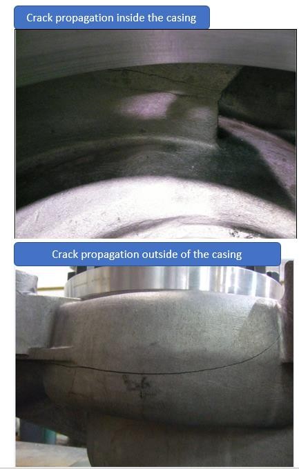
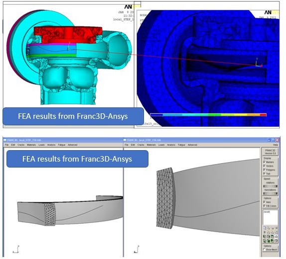
Failure of a pump casing evaluated using fracture mechanics. The crack initiated at the tongue region and propagated along the casing volute; the 3D simulation reproduced the observed path.
Crack paths in a spur gear predicted for two rim backup ratios. A thick rim (mb = 3.3) gives tooth fracture; a thin rim (mb = 0.3) gives rim fracture. The simulation captures both.
Modal analysis identifies the excited modes and the vibratory stress. Flaws are inserted at the critical locations of the blade and grown under that stress to give the number of cycles to the critical length.
A crack at an eccentric pin hole of a gas turbine casing is grown through the stress field of the casing. The stress intensity rises, peaks and then falls below the threshold, which shows where the crack arrests.
Standard cracked geometries from public test standards and the API 579 solution library, used to verify our models before they are applied to a project.
Typical assignments by industry, and published benchmark problems used to verify the calculations.
A 2.5 mm deep surface flaw at the longitudinal seam of a pressure vessel. Each pressure cycle extends the flaw; depth and length grow together and every step is checked on the Level 2 FAD.
Illustrative case: vessel of the published API 579-2/ASME PTB-14 example; flaw size and pressure chosen for illustration.
Case videos · select a category
A 2.5 mm deep surface flaw at the longitudinal seam of a pressure vessel. Each pressure cycle extends the flaw; depth and length grow together and every step is checked on the Level 2 FAD.
Illustrative case: vessel of the published API 579-2/ASME PTB-14 example; flaw size and pressure chosen for illustration.
A quarter-circular crack at the inside corner of a nozzle, driven by pressure and thermal stress. The corner-crack solution follows the front around the corner until the solution limit.
Illustrative case computed with PY-FFS; dimensions, loads and material data chosen for illustration.
A circumferential flaw at an as-welded girth weld. Bending cycles from a free span grow the flaw while pressure and weld residual stress stay in the FAD check.
Illustrative case computed with PY-FFS; dimensions, loads and material data chosen for illustration.
A weld flaw in a tank shell. Toughness from the ASME Section XI curve rises with temperature; the FAD point enters the acceptable region at the minimum safe metal temperature.
Illustrative case computed with PY-FFS; dimensions, loads and material data chosen for illustration.
A surface flaw at a weld of a pressurised sphere. An environment factor on the growth rate represents the service; the flaw is tracked through the wall.
Illustrative case computed with PY-FFS; dimensions, loads and material data chosen for illustration.
A flaw at the toe of an attachment fillet weld under thermal cycles. This video covers the fatigue part; creep damage is assessed separately to API 579 Part 10.
Illustrative case computed with PY-FFS: fatigue part only; creep damage is assessed separately (API 579 Part 10).
A straight-front crack at the thread root of a Ø50 mm stud under axial load and bending. The crack grows across the section until the FAD limit.
Illustrative case computed with PY-FFS; dimensions, loads and material data chosen for illustration.
A 3D model of a brace-to-chord T-joint with an initial flaw at the hot spot of the weld intersection. The crack front is advanced step by step and the stress intensity factors are extracted at each step.
Finite element crack growth simulation by Pythagoras Engineering (ANSYS).
A crack inserted at the tooth root of a spur gear is grown in the 3D model for two rim thicknesses. A thick rim gives tooth fracture, a thin rim gives rim fracture.
Finite element crack growth simulation by Pythagoras Engineering (ANSYS).
An axial crack is inserted in the 3D model of the shell and grown step by step; the stress field shows the concentration at the two crack tips.
Finite element crack growth simulation by Pythagoras Engineering (ANSYS).
Thermal and pressure cycles at a nozzle corner. A 3D crack model provides the driving force around the corner; growth sets the inspection interval to the next turnaround.
Pressure, bending from spans and settlement, and as-welded residual stress act together. The weld residual stress profile and toughness determine whether a repair is required.
Old shell plate, low metal temperature and a weld flaw. Toughness from Charpy data, the Master Curve and constraint set the minimum safe temperature.
Environment-assisted cracking at welds of a pressurised sphere. We assess the flaws found and the growth rate to support continued operation.
Creep and fatigue at a branch weld. Remaining life combines creep damage with crack growth between outages.
Cracks at shoulders, keyways and threads under bending and torsion. Round-bar and bolt solutions or a 3D model give the safe running period.
Illustrative case types. Project case studies are published with the permission of the equipment owner.
Results for published example problems of API 579-2/ASME PTB-14, computed with our in-house software. The values agree with the published results; small differences come from rounding in the published hand calculations.
Practical courses built from real assessments. Each course mixes the theory with worked examples, so participants can apply the methods to their own equipment. Delivered at your site or online, and tailored to your plant and procedures.
The assessment levels, the damage mechanisms and the data each part needs, with worked examples from the API 579-2/ASME PTB-14 example problems.
Stress intensity, J-integral, the failure assessment diagram, toughness and residual stress, explained for practising engineers.
Fatigue and environment-assisted crack growth, load spectra, remaining life and setting inspection intervals.
From Charpy energy to fracture toughness, the Master Curve and minimum safe temperature.
Crack insertion, crack-front meshing, K and J extraction and crack growth simulation, with hands-on exercises.
A course built around your equipment, codes and inspection findings, from a half-day briefing to a full workshop.
Course content and duration are adapted to each group. Use the enquiry form and choose "Training or workshop".
Short, practical papers based on assessments and simulations we have carried out, written for plant engineers and inspectors. Request a copy and we will email it to you.
How a crack that started at the tongue of a pump casing was reproduced with a 3D model, and what the growth life meant for the repair decision.
Request the paper →The effect of the rim backup ratio on the crack path: when a thin rim turns tooth fracture into rim fracture.
Request the paper →Building the 3D model of a brace-to-chord joint, inserting the flaw at the hot spot and growing it under wave loading.
Request the paper →An axial crack grown through the 3D model of a multilayer vessel, and the stress field at the two crack tips.
Request the paper →Why the stress intensity rises, peaks and falls below the threshold, and how that predicts where the crack stops.
Request the paper →Ask to be added to the distribution list. New papers from our project work are added here as they are released.
Join the listWe develop engineering calculation software around your own products, standards and procedures: design and rating calculations, assessment tools for your equipment, and tools that turn test or field data into decisions. Each tool is verified against benchmarks or your test data, documented and handed over with training.
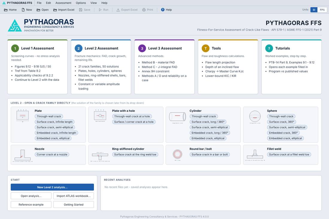
Our in-house software for fracture mechanics assessment to API 579-1/ASME FFS-1 Part 9, from Level 1 screening to Level 3, with crack growth analysis and remaining life. Every release is verified against the published API 579-2/ASME PTB-14 example problems.
We combine full-fledged in-house software with advanced simulation and code expertise, so each assessment uses the method that fits the problem.
A complete fitness-for-service software covering 21 flaw families and three assessment levels, verified against published benchmarks.
Fracture mechanics, 3D crack growth simulation, finite element analysis and the API 579 / ASME codes, in one team.
Simulation checked against experiments and code examples before it is applied to your equipment.
Results your inspection team and third-party reviewers can follow, with every assumption stated.
The same route for a single flaw or a plant-wide campaign.
We are an engineering consultancy dedicated to fitness-for-service and fracture mechanics, offering consultancy, corporate training and custom engineering software. We help operators of pressure equipment and rotating machinery keep damaged components in safe service, with assessments that are transparent, traceable to the codes and supported by our in-house software.
Our work ranges from screening a single inspection finding to 3D crack growth simulations and life-extension studies for refining, petrochemical, oil and gas, power, hydro, fertiliser and storage facilities.
Consultancy projects, corporate training and custom software. For a project, tell us about the inspection finding and the operating conditions; we reply with the assessment route, the data we need and a time estimate. Drawings and reports can follow by email.